
Once the sensors are in and the channels declared, the NAVIA EMU works on its own. It measures continuously, colours every value according to the thresholds you set, drives the panel annunciators, computes fuel used and endurance, and records the flight. Nothing has to be started, and the Configuration Portal does not need to be open.
This article covers what the system does with those numbers in flight, and the three setup jobs that decide whether it does anything useful: the alert thresholds, the fuel tank calibration, and the engine RPM minimum that quietly governs the logbook. The portal is a setup tool, not a cockpit instrument — avoid opening it in flight, and never save configuration changes there while airborne, because thresholds and calibrations take effect immediately and would change the alerting you are flying with.
Master Warning and Master Caution
Where the installation includes panel annunciators, the EMU drives them straight from the configured thresholds.
- A parameter entering its yellow range lights the amber Master Caution.
- A parameter entering its red range lights the red Master Warning.
- A failed sensor on a configured channel also lights the Master Caution. A lost indication is a condition in its own right, not a non-event.
Pressing the corresponding push-button acknowledges the alert: the lamp goes out while the condition persists. The acknowledgement re-arms itself when the condition clears, so the next excursion — the same parameter or any other — lights the lamp again. The parameter that caused the alert stays coloured on the display pages throughout, so acknowledging a lamp never hides the condition behind it. On a NAVIA display the same event appears as a MASTER WARNING or MASTER CAUTION banner at the top of the screen.
The annunciators are supervised: if the alerting inside the unit stops, the Master Caution lights by itself. A dark panel therefore genuinely means "no active alert", never "alerting failed silently".
On any alert, identify which parameter is out of range on the engine page, cross-check it against the aircraft's own engine instruments, and follow the procedure in the flight manual. Acknowledge the lamp after you know the cause, not before.
An indication in the red range may be a real engine problem or a failed sensor. Treat it as real until proven otherwise: confirm it against the aircraft's primary instruments and against the other engine parameters, remembering that a genuine overheat normally shows on more than one channel.
When a reading goes missing in flight
A broken sensor, a chafed wire or a loose connector eventually produces nonsense rather than nothing. When a channel delivers several consecutive bad readings, the EMU marks it invalid, shows it as N/A instead of a number, and stops generating alerts from it. Everything else carries on: the other channels keep working, their alerting stays live, and the flight keeps recording.
Note which channel failed and roughly when — the log file makes it easy to find afterwards — and cover the missing parameter with the aircraft's own instruments for the rest of the flight. Investigate on the ground, not in the air. A channel showing N/A is not an exceedance, which is why it lights the Master Caution rather than the Master Warning: no limit is known to be exceeded, but you have lost an indication and deserve to know.
The fuel computer
With a fuel flow channel configured, the EMU keeps two derived values alongside the measured ones, both shown in the Fuel computer card and on the displays.
- Fuel used — consumption since the totaliser was last reset, integrated from net flow, which is flow in minus return flow where a return channel exists. The counter survives power cycles. Reset it after refuelling with
Reset fuel used, exactly like a trip odometer. - Endurance — remaining sensed fuel divided by the current burn rate, in hours and minutes. It stays blank while the engine is not burning fuel, below roughly 1 l/h, so it cannot show absurd figures during taxi.
Endurance alerts on fixed boundaries that you cannot edit: yellow below 45 minutes, red below 30 minutes at the current burn rate. A red endurance lights the Master Warning like any other red-range parameter.
Both values inherit every error of the flow transducer and the tank probes, and endurance assumes the current burn rate continues — it shortens the instant you add power. Plan fuel by time and consumption as the flight manual requires, and use the fuel computer as a cross-check, never as the plan.
Calibrating a fuel tank
Tank geometry makes sender output non-linear, so every fuel quantity channel has to be taught its own tank against known amounts. The Calibration page appears in the navigation bar only when at least one fuel quantity channel is configured — if you cannot find it, that is why.
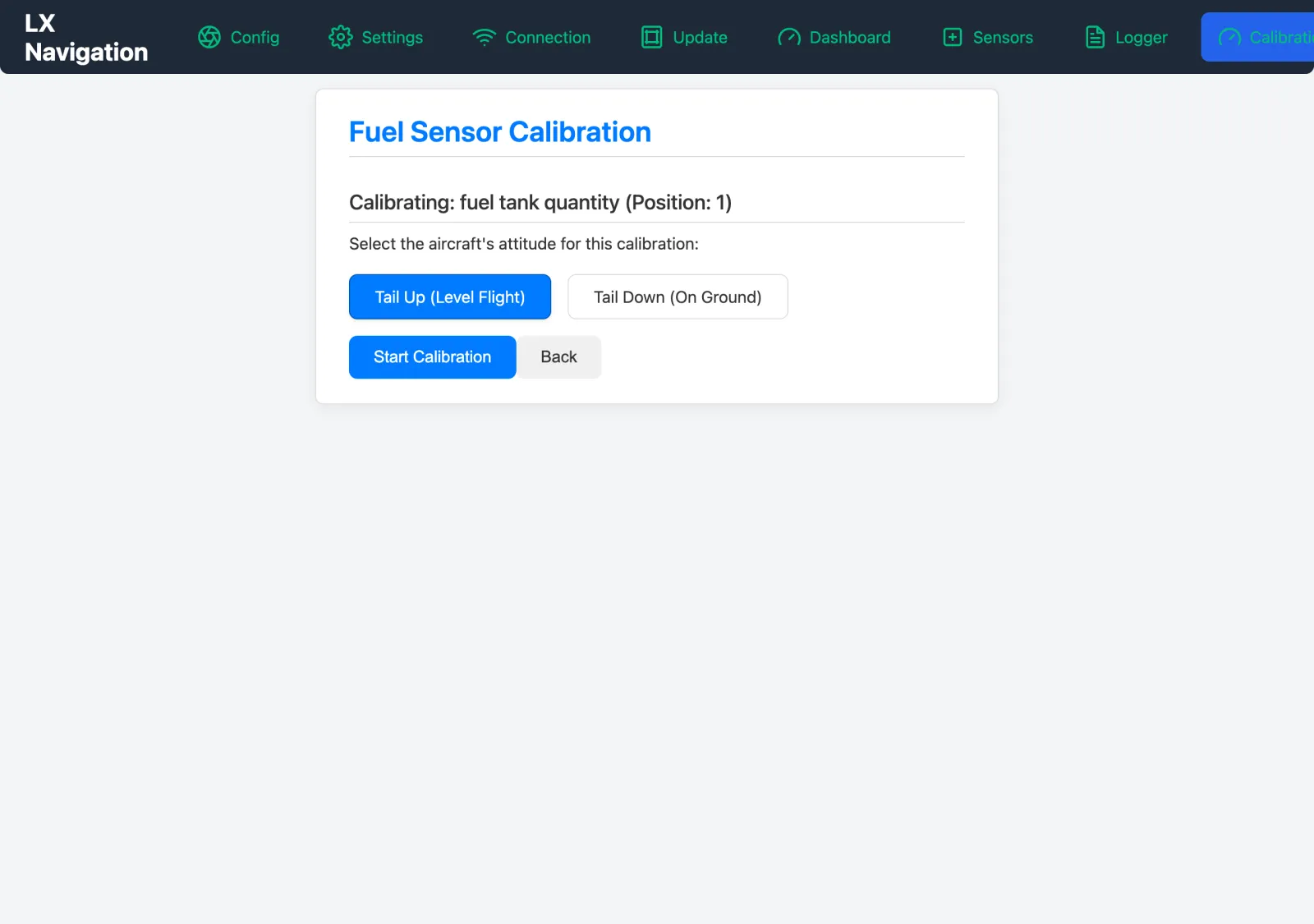
- Select the tank to calibrate.
- Select the attitude case —
Tail Up (Level Flight)orTail Down (On Ground). Taildraggers get both. - Press
Start Calibrationand choose the units you will work in. - Start with a genuinely empty tank: enter
0and pressAdd Pointwhile the live sensor value is shown. - Add fuel in known increments, entering the running total and pressing
Add Pointafter each, up to full. - Press
Finish & Save. The EMU builds the curve from the points you captured.
Points can be removed individually while you are calibrating. Use more increments where the sender is least linear — for most tanks that means the first and the last quarter, which is also where an error matters most.
Alert thresholds
Each measurement group carries six boundaries — Minimum, the four colour transitions, and Maximum — and they define the coloured ranges shown in the portal, on the displays, and driving the annunciator outputs. Zone checkboxes turn colour zones on and off, because not every measurement needs all of them: fuel quantity typically has no upper caution or upper red at all. Numeric fields set each boundary in the currently displayed unit, or you can drag the markers on the bar directly.
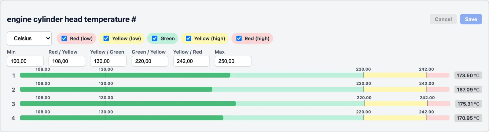
Nothing is stored until you press Save in the panel header. The editor flags implausible entries, such as boundaries out of order, but it will not stop you saving them.
Threshold values drive cockpit warnings directly. Verify every one against the engine manufacturer's published operating limitations before flight.
The factory defaults are not your limits
A measurement group gets these values when it is first configured. They exist so a freshly configured channel draws a sensible bar, and for no other reason.
| Measurement | Min | R→Y | Y→G | G→Y | Y→R | Max |
|---|---|---|---|---|---|---|
| CHT (°C) | 100 | 108 | 130 | 220 | 242 | 250 |
| EGT (°C) | 500 | 520 | 580 | 820 | 880 | 900 |
| TIT (°C) | 500 | 520 | 580 | 820 | 880 | 900 |
| Oil temperature (°C) | 75 | 79 | 90 | 135 | 146 | 150 |
| Manifold temperature (°C) | 5 | 6 | 9 | 26 | 29 | 30 |
| Coolant temperature (°C) | 50 | 53 | 60 | 90 | 97 | 100 |
| Oil pressure (hPa) | 0 | 400 | 1600 | 6400 | 7600 | 8000 |
| Manifold pressure (hPa) | 500 | 535 | 640 | 1060 | 1165 | 1200 |
| Fuel pressure (hPa) | 0 | 150 | 600 | 2400 | 2850 | 3000 |
| Coolant pressure (hPa) | 0 | 150 | 600 | 2400 | 2850 | 3000 |
| Fuel quantity (l) | 0 | 10 | 25 | 100 | — | — |
| Fuel in (l/h) | 20 | 22 | 27 | 61 | 66 | 68 |
| Fuel return (l/h) | 6 | 7 | 8 | 19 | 20 | 21 |
| Engine RPM | 800 | 895 | 1180 | 2320 | 2605 | 2700 |
| Rotor RPM | 92 | 103 | 125 | 278 | 300 | 311 |
| Voltage (V) | 12.0 | 12.1 | 12.4 | 13.6 | 13.9 | 14.0 |
| Current (A) | −10 | −8 | −4 | 4 | 8 | 10 |
| OAT (°C) | −40 | — | — | — | — | 55 |
These are generic starting points, not limits for your engine. Replace every one of them with the limits published in your engine's operating manual before flight.
Outside air temperature is informational by default: its caution and warning zones are disabled and the outer values only scale the bar. Fuel quantity has three zones rather than five, which is why its last two columns are empty. Values are listed in the EMU's base units and converted to whatever unit you have selected for that group.
The engine logbook, Hobbs and Tach
Recording is automatic. For every engine run the EMU creates a logbook entry with the daily flight number, engine start and stop, blocks-off and blocks-on, takeoff and landing times, plus a data file sampling every configured channel. Entries are listed on the Logger page and downloaded as CSV, which opens straight into a spreadsheet. The EMU also keeps Hobbs time — engine-on hours — and Tach time, weighted by RPM against your configured cruise RPM.
All of it hangs on one number. Recording starts when engine RPM rises above the Minimum boundary configured for the Engine RPM channel, which makes that value far more than a display limit: set it above windmilling and starter speed, and below idle.
With no Engine RPM channel configured, or its
Minimumset wrongly, flights may not be recorded. Check the logbook after the first flight rather than discovering the gap a season later.
Downloaded logs are the most underrated maintenance tool in the system. Trends in CHT and EGT spread, in oil pressure, and in charging current usually show a developing problem long before anything crosses a threshold.
When the library has no entry for your sender
Most senders are already in the built-in sensor library, selected by model number on the Config page. Where yours is not — bus voltage and many fuel quantity senders have no built-in entry — press Create New on the Sensors page, name the sensor, tick the measurement types it can serve, and choose the port group that matches its electrical type, because the group also tells the EMU how to drive the input. Then enter the transfer characteristic as a table of interpolation points, pairing raw electrical value with actual physical value; the EMU interpolates linearly between them, so use more points where the curve bends. With the channel already wired, Autofill From Sensor reads the live raw value into the field for you.
Fuel quantity senders are the exception: do not give them interpolation points here. They are calibrated tank by tank on the Calibration page.
Backups, updates and starting over
Under Settings › Local File Management the complete configuration — sensors, positions, thresholds, custom curves, calibrations, units, protocols — exports to a single JSON file and imports back onto the same or another EMU. Export after commissioning and keep the file with the aircraft records; export again before any firmware update or configuration experiment. Preparing one aircraft and importing onto its sister ships is the fastest way to configure a fleet. Importing loads the file into the portal only, so press Save on each affected page afterwards to write it to the device.
Firmware arrives as a single package containing all parts of the system, uploaded on the Update page. In a complete NAVIA system the Core Pro distributes updates to connected devices instead, in which case follow the system update procedure.
Keep the system powered for the whole update. Interrupting power partway through can leave the device inoperative.
A saved configuration is also what makes a factory reset survivable: the reset wipes channels, thresholds, calibrations, custom sensors and the Hobbs and Tach readings, and re-importing restores everything except those two counters, which you type back in by hand.
When something is not right
| Symptom | Probable cause | Remedy |
|---|---|---|
| Hotspot not visible | EMU not powered, or it has joined a saved network | Check system power; look for it on your local network instead |
| Portal does not open after joining the hotspot | It never opens by itself | Browse to 192.168.4.1 |
| Hotspot visible but the portal address does not load at all | The portal is served from the device's storage card | Power-cycle the system; if it persists, contact support |
| Portal loads but shows no data | Browser holding an old session | Reload the page; reconnect to the network |
| Update page rejects the package | Wrong or damaged file | Use the unmodified .zip from LX navigation |
| Dashboard says no sensors configured | No channels defined yet | Configure them on Config |
| A reading is implausible | Wrong sensor model selected for the channel | Match the library entry to the sender, or build a custom sensor |
Port is already used on a sensor card | Two channels assigned to the same input | Correct one of them |
| Changes lost after leaving a page | The card's Save was never pressed | Press Save on every card you touched |
| Imported configuration not active | Import loads into the portal only | Press Save on the affected pages |
| Sensor list empty for a measurement type | No built-in entry exists for it | Create a custom sensor, then select it |
| Calibration page missing | No fuel quantity channel configured | Add the channel first |
| Logbook empty after a flight | Engine RPM channel missing, or its Minimum set too high | Configure the channel; set Minimum below idle RPM |
If it persists, export the configuration, note the serial number, and talk to us.
Where to go next
- The sensor end of the installation, and what makes a channel trustworthy: installing CHT, EGT, RPM, fuel-flow and fuel-quantity sensors.
- The reasoning behind the numbers: the Academy articles on engine monitoring and fuel planning.
- Firmware, databases and the rest of the system: updates, databases and remote support and the seasonal firmware check.
- The device itself: NAVIA EMU.