

EMU
The engine monitoring unit of the NAVIA family. Engine parameters stream live into your displays — clearly visualized, logged and watched by alerts.
Documentation →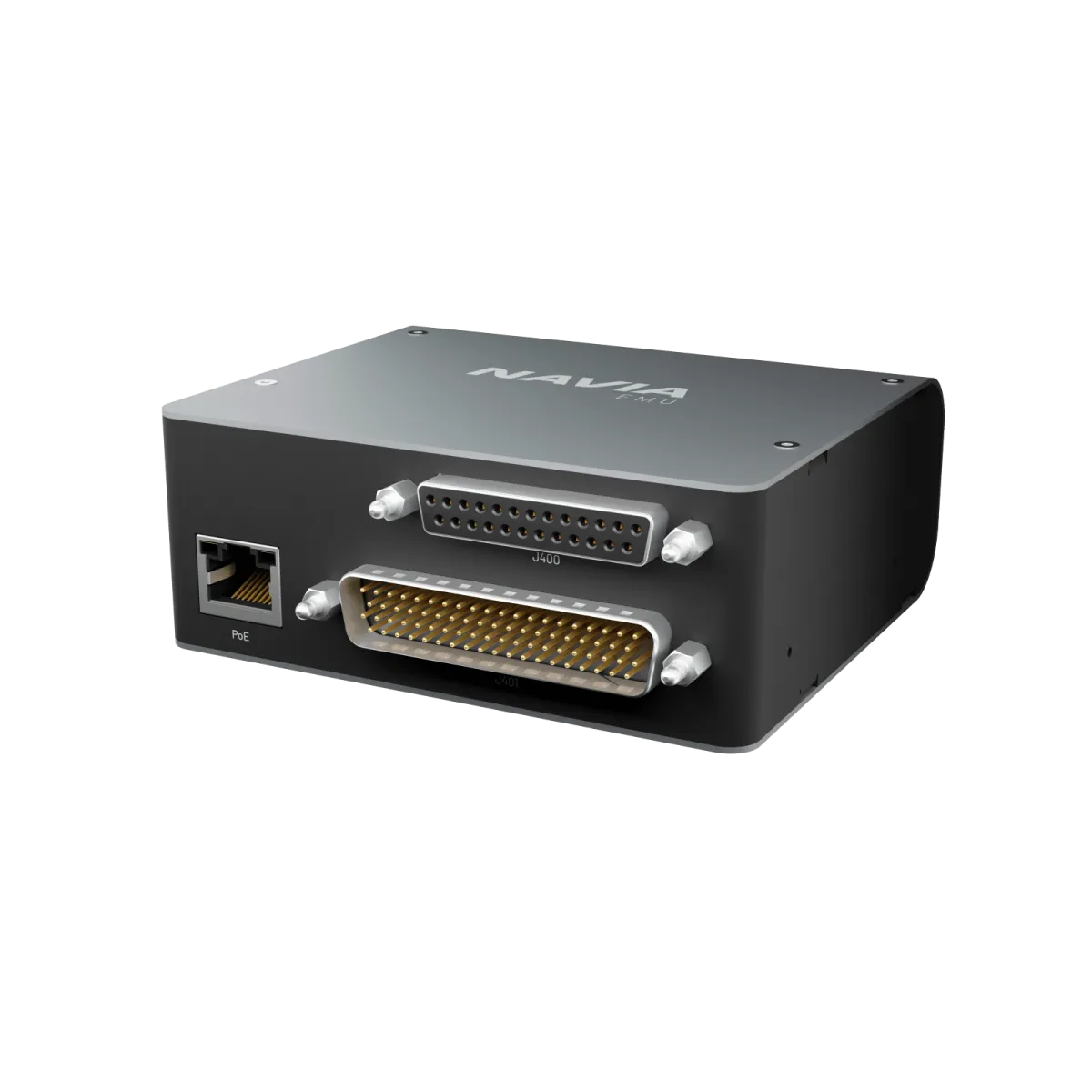
Under the cowling
RPM, temperatures, pressures and fuel data rendered in real time on any Navia Display.
Limits are monitored continuously — exceedances announce themselves before they become expensive.
Engine data is recorded alongside your flight log for trend monitoring and maintenance.
Every engine sensor, on one network cable.
The EMU reads the sensors of the engine and puts them on the Navia network: gauges on any display, limits in the colours of your own engine, alerts and a fuel computer. It is powered by its PoE cable and needs no connection to the aircraft bus.
Technical specification
- Thermocouple inputs
- 12 + 2 auxiliary, type J or K
- Resistance thermometer inputs
- 3 × Pt100 / Pt1000
- Universal sensor inputs
- 12 — resistive, 0–5 V, frequency or PWM
- RPM inputs
- 2
- Current measurement
- 300 A Hall-effect clamp
- Power supply
- PoE, from the Core Pro or the Hub
Navia is not TSO or ETSO approved. It is intended for VFR flight in gliders, motorgliders, ultralights, light-sport and experimental aircraft.
In the box
- Navia EMU
- Device registration card
- 4 mounting screws, fitted
You will also need
- Sensors and probes for your engine
- Thermocouple extension wire of the matching type
- Mating connectors and wiring
- PoE cable — 0.4, 1, 3 or 5 m
Good to know before you install.
- 01Mount the EMU on the cabin side of the firewall, as close to it as practical, and seal every firewall penetration fireproof.
- 02Extend thermocouples only with wire of the same type. Never shorten a probe lead and never solder in a thermocouple circuit.
- 03A magneto P-lead is never connected to an RPM input directly: it needs a 33 kΩ series resistor.
- 04Current is measured with the Hall-effect clamp. Shunt ammeters are not supported.
- 05A twin gets one EMU per engine.
- 06The EMU is an advisory system. It does not replace the engine instruments your aircraft is required to carry.
This is an overview, not the installation manual. The manual for your unit governs the installation — follow it, or have an LX dealer do the work.
Questions pilots ask.
Which engines does the EMU work with?
Any piston engine — Rotax, Jabiru, Lycoming, Continental, UL Power and others. Its inputs are configured for the sensors your engine has, not fixed to one engine type.
Can I reuse an existing thermocouple harness?
A GRT EIS thermocouple harness plugs straight into the 25-pin connector of the EMU.
Does the EMU need aircraft power?
No. It is powered through its PoE cable from the Core Pro or the Hub.
What does the EMU warn me about?
Every measurement has its own limits. Crossing one raises Master Caution or Master Warning on the displays, and the fuel computer warns when endurance runs low.
Does it keep an engine logbook?
Yes. Engine runs are logged automatically, with Hobbs and tach time, and the log can be downloaded as a CSV file.
Put it in a system.
Tell the configurator what you fly and how much panel you have. It puts the Navia system together, with prices.