
The NAVIA EMU is engine-agnostic. Nothing in it is hardcoded to a particular powerplant: every input is declared in the Configuration Portal rather than at the factory, and virtually any industry-standard sender can be connected and calibrated. That freedom lands entirely on whoever does the installation.
This article covers the sensor end of the job — where each probe goes, what it must never be wired with, and what to check before the aircraft flies again. The EMU-side pin allocations are in the installation manual and are not repeated here. What follows is the part that is the same in every aircraft: the physics that decides whether a channel is telling you the truth.
What you are wiring into
| Input group | Count | Takes |
|---|---|---|
| Thermocouple, differential (J400) | 12 | Type J or K probes — CHT, EGT, anything thermocouple |
| Thermocouple, auxiliary (J401) | 2 | TC13 differential, TC14 single-ended — normally turbine inlet temperature |
| RTD | 3 | Pt100 / Pt1000 — outside air, oil, carburettor |
| Analogue / digital (AIN) | 12 | Resistive senders, active 0–5 V sensors, pulse and frequency signals |
| RPM | 2 | Engine and rotor or propeller |
| Current clamp | 1 | Hall-effect DC clamp |
Alongside these sit internally generated, individually fused +5 V and +12 V supply rails for the senders themselves (plus a 3.3 V rail for the current clamp), and the Master Warning and Master Caution lamp outputs and acknowledge-button inputs. Every channel is declared on the portal Config page — port, sensor model from the library, measurement type and position — so no input is committed to anything until you say so.
The thermocouple rule that governs everything
A thermocouple generates its signal at the junction of two dissimilar metals, which means every additional dissimilar-metal junction in the circuit is a measurement error. Four rules follow, and none of them are optional.
- Matching extension wire. Type K extension wire for type K probes, type J for type J. Never extend a thermocouple with ordinary copper, and route the run away from ignition leads and alternator cables.
- Polarity, checked against the wire's own datasheet. The colour codes disagree between standards: in the American code red is always negative, in the European code white is always negative, and legacy national codes differ again — some of them using red as positive. A reversed pair does not damage the input, it just makes the reading fall as the probe heats up.
- Crimp, never solder. Thermocouple wire does not solder well, and a soldered joint is a rigid point for vibration to work on. Solder-cup connectors are out for the same reason.
- Put the cold junction at J400. The thermocouple-to-copper transition belongs in the connector, where the EMU measures its reference temperature.
A copper splice made somewhere convenient in the engine compartment reads perfectly on the ground and drifts by tens of degrees in flight, as the splice and the connector diverge in temperature. It is the single most common way to get a plausible, confident, wrong number.
CHT probes
Ring-terminal probes
Remove the spark plug, place the ring probe under it, refit the plug. Orient the probe so its leads have the maximum available clearance from the exhaust and from engine structure.
Bayonet probes
Screw the bayonet adapter into the threaded CHT well near the bottom spark plug. Adjust the locking collar on the spring so the probe tip presses firmly on the bottom of the well when locked.
The CHT well is identified by its solid bottom. Never use the primer hole: it is open into the cylinder. If you cannot tell the two apart on this engine, stop and consult someone who can.
Rotax under-bolt probes
On 912-series engines the stock CHT senders can be replaced by 10 mm ring probes fitted under the original sensor bolts, following the engine maker's guidance.
EGT probes
Where the engine manufacturer gives no guidance on probe location:
- Drill a 1/8-inch hole in each exhaust pipe, 2–8 inches from the cylinder — and, far more important than the exact figure, the same distance on every cylinder, because the whole value of EGT is in comparing one cylinder against its neighbours.
- Choose a straight section of pipe rather than a curve; the clamps seat properly there. Check the probe will not foul the cowl or block maintenance access.
- Insert the probe and tighten the clamp firmly, without over-tightening.
The probe body grounds through the exhaust pipe. That is normal and required for a stable reading. Leave slack in the leads between engine and airframe to absorb engine movement, and label every lead with its cylinder number before you route it — sorting that out later, on your back, in the dark, is nobody's idea of an afternoon. Do not cut probe leads to length: coil and secure the excess instead. Unused thermocouple inputs need nothing done to them, though for the tidiest readings unused pairs may be shorted together at the connector.
A loose or detached EGT probe leaves an open hole in the exhaust, leaking hot gas and carbon monoxide into the cowling. Inspect the attachment at every inspection. On pusher installations, safety-wire the probe so a failed clamp cannot let it reach the propeller.
RTD, fluid and pressure senders
Outside air temperature from a Pt1000 probe on an RTD input needs no interface network, and placement decides the reading: out of the propeller wash and the exhaust stream, away from cowling outlets and heated skin, never behind the engine, not inside a NACA inlet, and preferably in the shade rather than under a fairing that bakes in the sun. An inspection cover under the wing, outside the propeller wash, is a reliable spot. Twist the probe leads over their full length.
Fit fluid temperature senders per the engine manufacturer's instructions. Single-terminal senders ground through their own case, so the case must have a good electrical connection to engine ground — use pipe thread sealing compound, not PTFE tape, which insulates. Two-terminal senders take their return to the channel ground pin.
Resistive pressure senders ground through the case too, so a remote-mounted one needs a dedicated ground wire back to it. The VDO 0–2 bar low-pressure sender is vibration-sensitive: mount it remotely on the firewall and reach the pressure with a hose. Active 0–5 V transducers mount with the threaded port down or horizontal, never pointing up, so water cannot collect inside and split the sensor when it freezes, and they are powered from the EMU's fused supply pins only; some are destroyed by direct connection to unregulated aircraft power.
Current-loop senders, including the current-production Rotax oil pressure senders that replaced the older resistive type, are read through an external shunt resistor: the loop current develops a voltage across the shunt, and the channel is configured as an active sensor with a custom two-point curve. If your engine carries the newer sender, the resistive wiring shown for the older one simply does not apply.
Fuel quantity probes
Resistive float senders wire straight to an AIN channel in resistive mode and are calibrated tank-by-tank on the portal Calibration page. Capacitive probes use their own interface module with a 0–5 V output, and must first be taught the tank with the probe manufacturer's own empty/full set-point procedure before the EMU channel is calibrated on top of it. Keep a capacitive probe tip at least 1/4 inch clear of the tank bottom, and expect readings to take up to two minutes to settle after fuelling — the damping is deliberate, not a fault.
Electric fuel quantity indication, float or capacitive, must never be the sole basis for fuel planning. Determine fuel on board before flight by dipstick or visual check, and plan by time and consumption. Senders stick, attitudes change, and fuel sloshes.
Fuel flow transducers
The EMU counts pulses from a turbine transducer — the reference EI FT-60 is linear to about one per cent — and it is utterly unforgiving about plumbing.
- Fit the transducer downstream of the last fuel pump. Upstream of a pump it invites vapour lock and jumpy readings.
- Give the inlet at least five inches of straight or gently curving line, and route the outlet level with or above the transducer — never dropping away immediately after it.
- Put a gascolator or filter upstream to keep debris out of the rotor.
- Mount it with the electrical wires pointing up, because the design vents vapour that way. Thread sealant on the ports is mandatory, but never PTFE tape, which shreds into the rotor.
- The EI FT-60 and other open-collector transducers need an external pull-up resistor of 4.7–10 kΩ to the channel's +5 V pin. Without it the channel reads zero flow, permanently and convincingly.
- After the fuel system is closed up, run the flow and pressure tests of FAA AC 23-16 — typically 125–150% of full-throttle fuel flow — and confirm system pressure stays above the engine minimum.
- If readings jump with the electric boost pump running, that is pulsation and not the transducer: a tee before it with 1–2 ft of capped tubing pointing vertically up will damp it.
- On return-line systems, a second transducer in the return line lets the EMU compute net consumption — configure the two channels as fuel in and fuel return.
RPM, supplies and annunciators
Two independent RPM inputs cover engine and rotor or propeller speed. They accept hall-effect sensors and low-voltage pulse signals — trigger-coil outputs, electronic tachometer outputs, gearbox pickups. Pulses per revolution and, behind a gearbox, the reduction ratio are set per channel in the portal, so a channel reading exactly double or exactly half is nearly always a settings error rather than a wiring one.
Never connect a magneto P-lead or an ignition high-tension lead directly to an RPM input. Magneto-equipped engines need the series-resistor connection given in the installation manual; the raw lead carries energy the input will not survive.
Sender supplies come from the EMU's own fused rails, so no aircraft bus power needs to reach the engine sensors at all. A dead supply pin is usually a resettable fuse that has done its job: remove the short and power-cycle. The Master Warning and Master Caution circuits give you both halves of a classic annunciator — an indicator output for the panel lamp and an input for a momentary acknowledge button — so a combined push-button with an integrated lamp wires straight in; take the lamp connection itself from the installation manual. In a Power-over-Ethernet installation the EMU has no connection to the aircraft bus at all, so bus voltage is monitored by bringing it in through a divider network to a spare AIN channel — never above 5 V directly onto an AIN pin.
Two worked examples
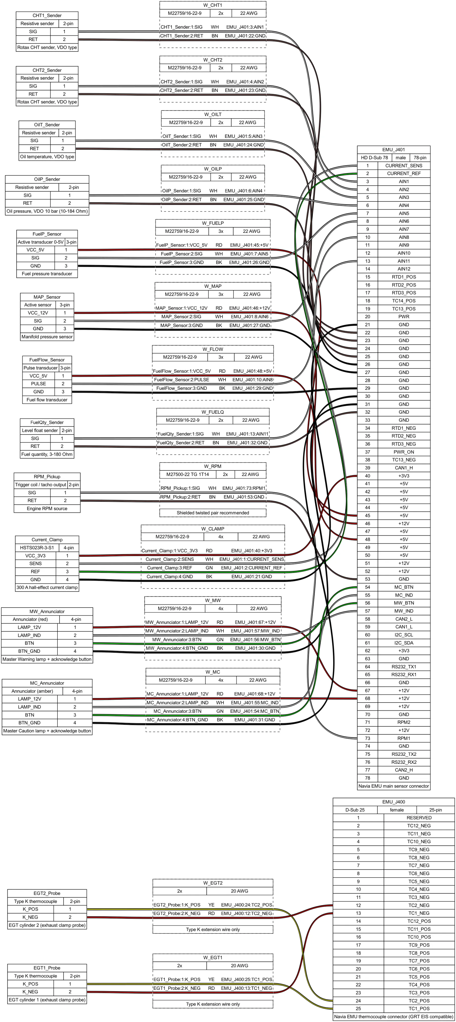
| Measurement | Rotax 912 ULS | Lycoming O-320 |
|---|---|---|
| EGT | Type K probes, TC1–TC2 | Type K clamp probes, TC1–TC4 |
| CHT | Resistive senders on AIN1–AIN2 | Bayonet probes, TC5–TC8 |
| Oil temperature | Resistive sender, AIN3 | Pt100 RTD, RTD1 |
| Oil and fuel pressure | Resistive sender and 0–5 V transducer, AIN4–AIN5 | Resistive senders, AIN1–AIN2 |
| Manifold pressure | Active 0–5 V sensor, AIN6 | Active 0–5 V sensor, AIN5 |
| Fuel quantity | Float sender, AIN11 | Float senders left and right, AIN11–AIN12 |
| Engine RPM | Trigger coil or tacho output, RPM1 | Electronic tach output or hall pickup, RPM1 |
| Fuel flow | Pulse transducer, AIN8 | — |
| Carburettor temperature | — | Pt100 RTD, RTD2 |
| Current | 300 A hall clamp, clamp input | 300 A hall clamp, clamp input |
Both are starting points: any input can be reassigned in the portal. The one allocation that is not yours to choose is a reused thermocouple harness from an existing engine information system — leave the harness alone and assign the channels to match how it is already wired.
Post-installation checkout
- Power up and confirm the EMU is announced to the system, or that the portal is reachable in a standalone installation. Verify the reported firmware version is current.
- Check plausibility cold. Every temperature channel should sit near ambient; a channel pegged full-scale or at zero is an open or shorted probe circuit, or the wrong sensor model selected. Pressure channels read zero. Fuel quantity matches what is actually in the tanks. System voltage matches a multimeter.
- Check thermocouple polarity by warming each probe individually and confirming the right channel rises. A channel that falls has its pair swapped.
- Exercise the alerting loop. Temporarily lower a threshold to force a caution and a warning, confirm the panel lamps light and the acknowledge buttons work, then restore the real thresholds and verify them again.
- Run the engine. RPM against a reference tachometer across the range (verify the reduction ratio setting), oil pressure up immediately after start, all CHT and EGT channels rising evenly, fuel flow plausible at idle and at run-up, charging current responding as loads are switched.
- Inspect afterwards for leaks at every fitting and boss, chafing along the harness, and firewall penetrations still properly sealed.
When a channel does not read right
| Symptom | Likely cause | Fix |
|---|---|---|
| Thermocouple channel pegged full-scale or blank | Open probe circuit — broken extension wire, bad crimp, unplugged probe | Check continuity probe to J400, re-crimp, confirm the pair is in the right contacts |
| Reading falls when the probe is heated | Reversed pair | Swap the pair at the connector |
| Plausible on the ground, tens of degrees out in flight | Copper splice or solder joint in the thermocouple path | Remove it; matching alloy wire end to end |
| One CHT or EGT channel erratic | Loose clamp, probe tip not grounded, or lead routed along ignition wiring | Re-tighten, reseat, reroute |
| Resistive sender reads with a large offset | Wrong sensor model selected, or a poor sender case ground | Check the model on Config; measure engine case to ground bus with all loads on — over 50 mV means a bad engine ground |
| All engine-grounded senders offset together | Voltage drop on the engine ground strap | Engine case to ground bus must read under 50 mV (ideally 20 mV) with everything on — fix the ground strap first |
| Active 0–5 V sensor stuck at maximum | Channel left in resistive mode, or a shorted supply pin | Set the correct mode; check the supply |
| RPM reads zero | Wrong source lead (Rotax trigger coil: try the other wire), missing external network, or wrong pulses per revolution | Verify the source for this engine; correct the portal settings |
| RPM erratic, or exactly double or half | Wrong pulses-per-revolution setting, or ignition interference | Correct the setting; reroute the RPM lead away from ignition wiring |
| Fuel flow reads high with the electric boost pump on | Fuel pulsation | Install a pulsation-damper tee before the transducer |
| Fuel flow always zero | Open-collector transducer with no external pull-up | Fit the pull-up to the channel's +5 V pin |
| Sensor supply pin dead | Resettable fuse tripped by a short | Remove the short, power-cycle |
| Master lamp permanently on | Threshold misconfigured, or lamp on the wrong pins | Review thresholds; verify the lamp wiring |
Where to go next
- Everyday operation, alerting, the fuel computer and tank calibration: NAVIA EMU in use.
- What the numbers mean once they are on the screen: the Academy articles on engine monitoring and fuel planning.
- Where the EMU sits in the aircraft: NAVIA system architecture, commissioning a new aircraft and the NAVIA EMU product page.
- Pin allocations, torque figures and anything mechanical: the installation manual, then your dealer, then us.