
Commissioning is the one part of a NAVIA installation nobody can do for you. A workshop can fit the hardware and pull the cables, but the numbers that make the system say anything useful — the polar, the certified speeds, the masses and the lever arms — come out of the aircraft flight manual and the current weighing report, and somebody has to type them in correctly.
This article walks the owner through that first-time configuration in the order it actually works: register the aircraft, sign in, describe the airframe, declare the devices, then check the result. Steps marked glider or motorplane apply to that aircraft type only; everything else applies to both.
Before you start
Have these to hand before you touch a screen:
- The aircraft flight manual — the aircraft category, speeds, load factors, limit masses, the C.G. envelope and the polar all come from it.
- The latest weighing report — empty mass and empty-mass arm, and nothing older than the last weighing.
- The Core's serial number — registering it to your LX Cloud account is what makes you the owner of this aircraft.
Everything below assumes the hardware is installed and wired as described in the NAVIA architecture article and the installation manuals.
The commissioning sequence
- Install and wire the hardware, per the installation manuals.
- Create your LX Cloud account and register the Core's serial number to it. This is the step that makes you the owner; ownership lives in the cloud, not in the aircraft.
- Sign in on the main display and tick
Remember me, so that screen logs you in at power-on from now on. - Set aircraft category, registration and call sign under
Airplane Settings › Aircraft. - Create a Configuration — preset or custom — under
Aircraft › Configurations. - Check or enter the polar under
Configuration › Polar parameters. (Glider and motor glider.) - Enter the flight-envelope speeds and, if fitted, the flap positions, under
Configuration › Flight envelope. - Enter weight and balance — masses, C.G. envelope, stations and seats — under
Configuration › Weight & Balance. - Declare the connected devices: radio, transponder, traffic, sensors, under
Airplane Settings › Devices. - Verify the EMU and its sensors appear and read correctly on the
Instrumentspage and the engine widgets. (Motorplane.) - Name the screens, set their Screen and Login Types and assign profiles, under
Airplane Settings › Screen Management. - Install databases and charts, and set your notifications and checklists, under
DatabaseandUser Settings. - Run the checks in the last section of this article.
Aircraft identity and configurations
Under Airplane Settings › Aircraft, set the Aircraft category first. It decides whether the glider tools — tasks, vario, final glide — or the powered-flight vocabulary of flight plans and engine instruments is active throughout the system, so getting it wrong changes every page you look at afterwards. Then set the Registration and Call sign, which appear on screen and in every recorded flight.
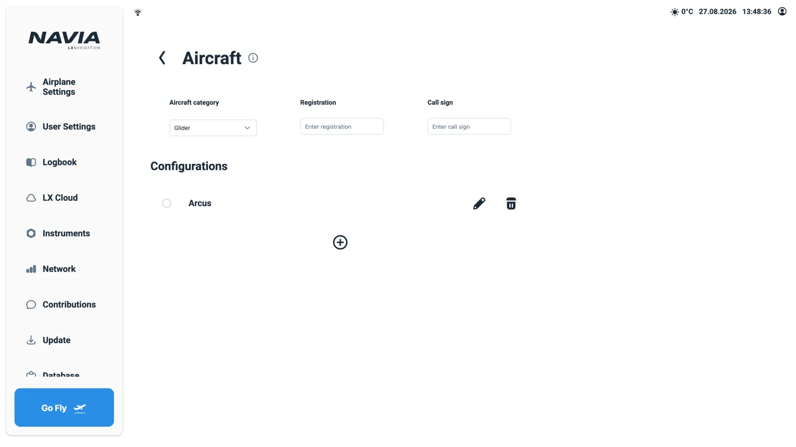
Then create a Configuration with the + button. A configuration is one validated aerodynamic and loading state of the airframe, so an aircraft can carry several — 15 m and 18 m tips, with and without winglets — and you switch between them instead of retyping numbers. Two paths:
- Preset (gliders) — choose your type from the built-in library and press
Use preset. Polar and reference data arrive pre-filled and you verify them against your flight manual. - Custom configuration — start empty and enter everything yourself. This is the usual path for powered aircraft.
Each configuration carries a Name, the competition Class, the Wing area used for wing loading, and the Handicap (DAeC) index, plus the three sub-pages below.
The polar
Applies to gliders and motor gliders. A pure motorplane can leave the polar fields as they are — the polar only drives the gliding calculations. Until a polar and an envelope are entered, the system flags the aircraft as not configured.
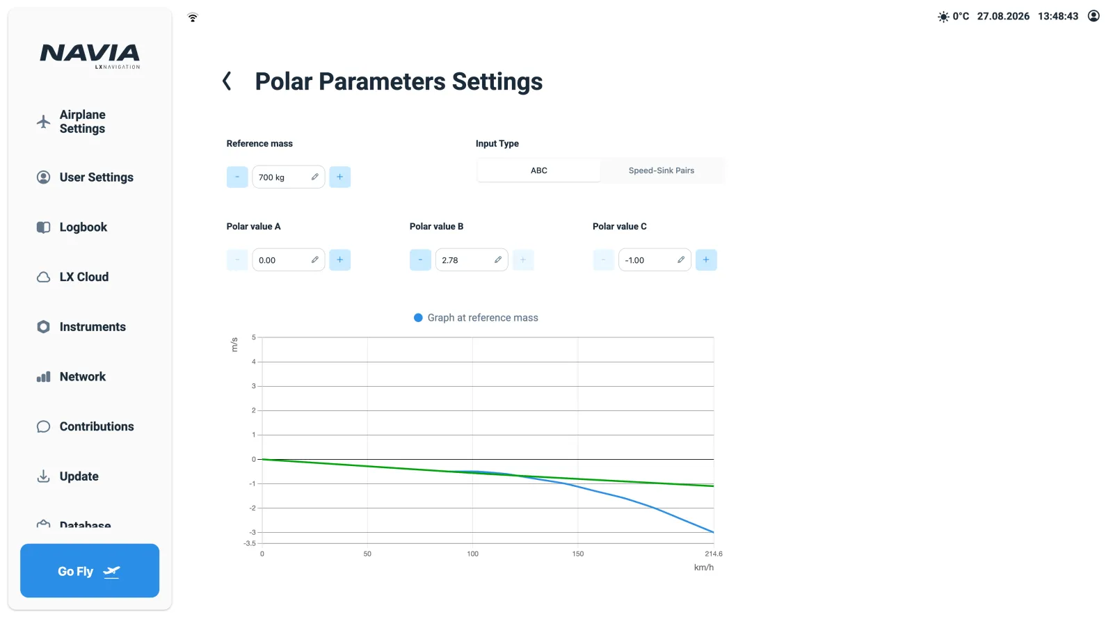
The polar is the performance model behind speed-to-fly, final glide, netto vario and the glide range drawn on the map. On a glider it matters more than any other single setting. On the Polar Parameters Settings page you enter:
- Reference mass — the mass at which the polar data is valid, from the flight manual or the preset. In flight the polar is shifted automatically for the actual mass, ballast and bugs.
- Input Type — either ABC, the quadratic coefficients entered directly if you know them (presets fill these in), or Speed-Sink Pairs, the practical path for a custom aircraft: read three speed/sink points off the flight-manual polar — one near minimum sink, one mid-range, one at high speed — and the coefficients are derived for you.
The graph at reference mass below the fields redraws as you type. Compare its shape and its numbers against the flight-manual polar before you accept it.
Bugs and water ballast are not configured here. They change flight by flight and belong in the vario tools panel on the Navigation display. The theory behind what these numbers do is in MacCready and speed to fly and polar degradation.
Flight envelope and flaps
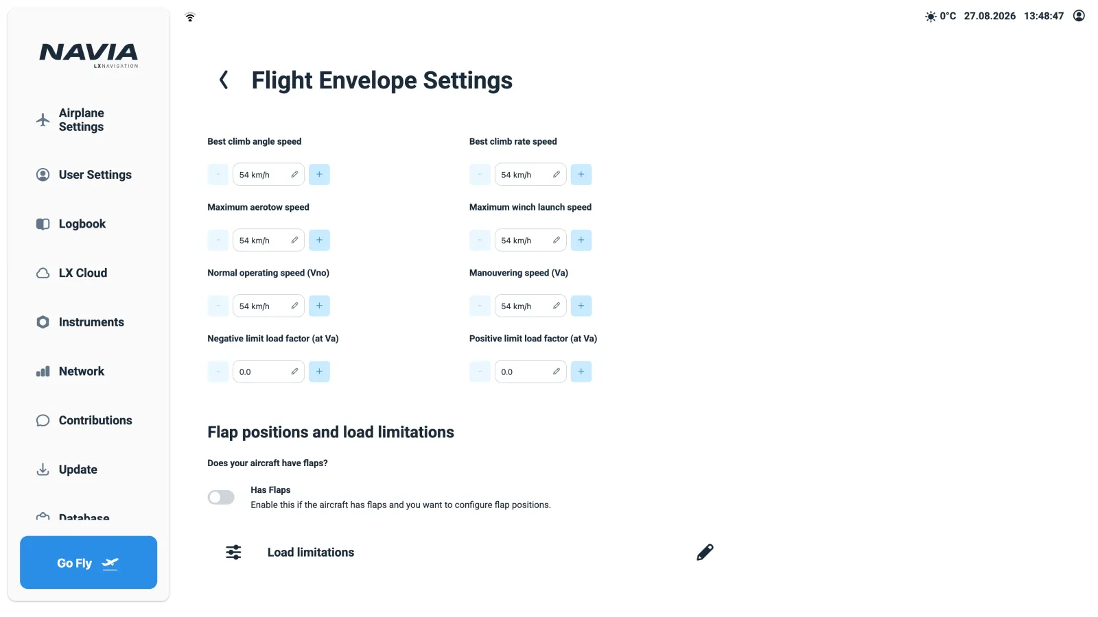
The Flight Envelope Settings page holds the speeds and load limits from the flight manual. They drive the speed-tape arcs on the PFD and the airspeed instruments, and the overspeed and stall warnings.
| Field | Used for | Applies to |
|---|---|---|
| Stall speeds, VNE, normal operating speed (VNO) | Speed tape arcs, stall and overspeed warnings | All |
| Manoeuvring speed (VA), positive and negative limit load factor at VA | Structural limits, G-load warning | All |
| Best climb angle speed, best climb rate speed | Climb-out reference | All |
| Maximum winch launch speed, maximum aerotow speed | Launch overspeed warnings | Glider |
| Flap positions | Per-flap speed ranges and flap warnings | Aircraft with flaps |
Enter these exactly as certified. The stall, overspeed and G-load warnings are all derived from this page, and a mistyped VNE produces an instrument that is confidently wrong at the worst possible moment.
If the aircraft has flaps, enable Has Flaps under Flap positions and load limitations and define each position with its speed range — VFE per position, and the recommended minimum and maximum speeds. On gliders each position can additionally set the SC mode: whether selecting that flap position switches the variometer to speed command, to vario, or leaves it unchanged. That is how the familiar "negative flaps cruise, positive flaps thermal" automation is built. For the system to know the actual position, connect the flap sensor or lever switch under Airplane Settings › I/O Configuration.
Why the load-factor limits deserve honest numbers is covered in gust loads.
Weight and balance
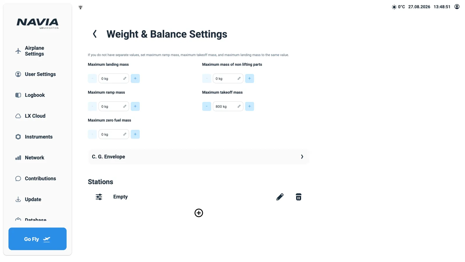
The Weight & Balance Settings page keeps the loading calculation honest, and feeds the C.G. out of limits warning. From the flight manual and the current weighing report, enter:
- Limit masses — maximum ramp, takeoff, landing and zero-fuel mass, plus the maximum mass of non-lifting parts (gliders). If your manual does not distinguish ramp, takeoff and landing mass, set all three to the same value; the page says as much.
- C.G. envelope — the certified centre-of-gravity limits over mass.
- Stations — one entry per mass item, each with its lever arm.
The station types
- Empty — empty mass and empty-mass arm from the weighing report. Update it after every new weighing.
- Person — one per seat. Link the station to a screen with
Select Screensand the pilot who signs in on that screen has their profile weight entered automatically; the seat markedPilot in commanddecides who is recorded as PIC. - Water — ballast tanks (gliders). The in-flight ballast setting in the vario tools refers to these.
- Fuel — fuel tanks (motorplanes). With an EMU fuel sender, quantity can follow the measured value.
- Baggage / Other — fixed or occasional loads.
If the arms and stations are new territory, read weight and balance before you start typing.
Which steps apply to which aircraft
| Step | Glider / motor glider | Motorplane |
|---|---|---|
| Polar | Applies — everything gliding depends on it | Leave as is — it only drives gliding calculations |
| Maximum winch launch and aerotow speeds | Applies | — |
| Water ballast stations, ballast dump temperature | Applies | — |
| Air brake warning | Applies | — |
| Fuel stations | Motor glider only, as fitted | Applies |
| EMU and engine sensor verification | Motor glider only, as fitted | Applies |
| Flap positions and SC mode | SC mode is glider-only | Speed ranges only |
Checks before the first flight
Work through all of these with the aircraft on the ground:
- The aircraft not configured indication is gone.
- The speed tape shows the correct arcs — green from VS1, yellow from VNO, a red line at VNE.
- Weight and balance shows the current loading inside the C.G. envelope, with you signed in.
- (Glider) The vario tools panel shows the polar curve and a plausible speed-to-fly for MacCready 0.
- (Motorplane) The engine widgets show live values with the engine running, and no red crosses.
- Radio and transponder respond from the screens, and the status bar shows every device healthy.
- Trigger a test warning — a low altitude or a gear reminder — to confirm the audio path works.
Where to go next
- How the units, cabling and power budget fit together: NAVIA system architecture.
- The theory behind the numbers you just entered: MacCready, polar degradation, weight and balance and gust loads.
- Anything the flight manual and this article disagree about: the flight manual wins. If the system still disagrees with both, talk to us.